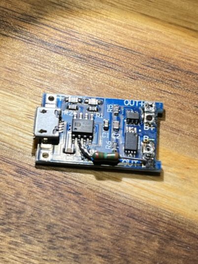
Brief service announcement on TP4056 based Lithium Ion charging modules from AliExpress: You need to configure them to your target batteries capacity. This is done by changing resistor R3 on them accordingly. Check out https://www.best-microcontroller-projects.com/tp4056.html for details.
If you don’t, this can lead to thermal runaway (aka setting stuff on fire) caused by overcharging the cell.
Water filters are essential devices that help remove impurities from water, ensuring clean and safe drinking water. Over time, these filters will become saturated with contaminants, leading to reduced efficiency. However, through the process of regeneration, water filters can be revitalized and reused, extending their lifespan and minimizing waste. In this post, I will explore how to regenerate simple cation resin cartridges using dishwasher salt, a cost-effective and readily available solution.
Understanding Dishwasher Salt
Dishwasher salt, also known as water softener salt, is a specific type of salt designed for use in dishwashers equipped with water softening systems. Unlike table salt, dishwasher salt is primarily composed of pure sodium chloride without any additives like iodine or anti-caking agents. Its main purpose is to regenerate water softeners by removing calcium and magnesium ions, which cause water hardness. This same principle of ion exchange makes it a suitable option for regenerating cation resin cartridges used in water filters.
Cation Ion Exchange and How It Works
Cation resin cartridges are used in water filters to remove positively charged ions from water, such as calcium (Ca2+), magnesium (Mg2+), and certain heavy metals. The resin within these cartridges is composed of small polymer beads, which are negatively charged and referred to as “cation exchange resin.” These negatively charged beads attract and trap positively charged ions as water passes through the filter.
As the cation resin beads capture these ions over time, they become saturated and lose their ability to efficiently filter water. This is where the process of regeneration comes into play. By using dishwasher salt, which is rich in sodium ions (Na+), we can trigger an ion exchange process to recharge the cation resin.
Regenerating Cation Resin Cartridges with Dishwasher Salt
Here’s a step-by-step guide on how to regenerate water filters with cation resin cartridges using dishwasher salt:
Step 1: Prepare the salt solution Take dishwasher salt and dissolve it in water to create a concentrated salt solution. The correct salt-to-water ratio is not that important. As a rule of thumb, make sure the cartridge is fully covered with a layer of salt.
Step 2: Fill the pitcher with tap water – add more salt if necessary. Just make sure it’s always covered with salt. The water should always be fully saturated with salt.
Step 3: Allow sufficient time Let the cartridge soak in the salt solution for at least 20 minutes.
Step 4: Give the Cartridge another run with salt solution. You can use the same water as used before.
Step 5: Rinse the cartridge After the soaking period, clean the cartridge from the salt solution and rinse it thoroughly with clean water. Rinse 3 pitchers or so. This step helps eliminate any excess salt and ensures the filter is ready for use.
Conclusion
Water filters (may) play a crucial role in maintaining water quality necessary to brew good coffee and tea. By understanding how to regenerate cation resin cartridges using dishwasher salt, you can prolong the life of your water filter and reduce the impact on the environment through reduced waste. It also helps you saving costs – OEM cartridges are not cheap! Regular regeneration helps your water filter perform optimally, providing you with clean and safe drinking water for an extended period. I guess this process can be repeated 3 to 5 times per cartridge before the resin degrades to an unusable level.
I’ve read many articles on how to build IoT projects with Arduino – most of them covered the basics of micro controllers and how to use them in a more or less useful scenario in your home (“Build a self watering plant with an Arduino”). I’ve always missed the HOW part. That’s why I want to summarize my own experiences and mistakes made. I want to give you some tips on how to avoid problems building very quick prototypes to try a certain use case. See this article as a collection of thoughts and not as the definite truth.
In my understanding, Rapid Prototyping is the process of building a working “system” of some sort in relatively little time with the goal of experiencing how this system feels in a certain scenario and learn from this experience. The outcome of this process is not a product but knowledge about usability, haptics and possible problems in operation and manufacturing.
With that said, let me summarize some of my thoughts:
Sketch your Ideas first!
Use existing modules
Aliexpress is your friend. I recommend getting a basic setup of those small and really cheap modules for your project domain. It won’t cost you a fortune to get a few. Always order a bunch – you will break stuff. And shipping from china takes a few weeks.
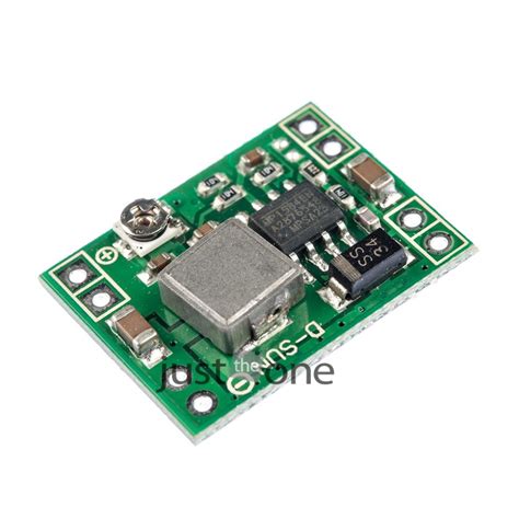
Often, people struggle with the power supply of your project. DC DC Buck converters allow you to transform a higher voltage from a variable input to your desired one. They cost about 0.30 Euro / piece and can be useful in cases where you need to run a 3.3V MCU on 12V DC.
The other way is also possible with a step up converter (sometimes referred to as boost converter). It lets you boost your voltage from a lower voltage to a higher one. For example, you have a USB powered device and you want to run a 12V Fan on it. On this 1.80 Euro module, the output voltage can be adjusted with the potentiometer.
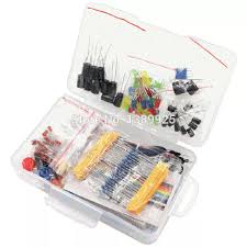
Get a bunch of capacitors and resistors. They are your friends. A good kit contains
470 μF (can minimize reset inducing voltage fluctuations)
0.1 μF (standard decoupling capacitor)
1 kΩ Resistor
10 kΩ Resistor (good Pullup for 5V apps.)
100
470 kΩ Resistor
4.7 kΩ Resistor
I found that 10 kΩ to 100 kΩ pullup resistors usually work fine in my circuits.
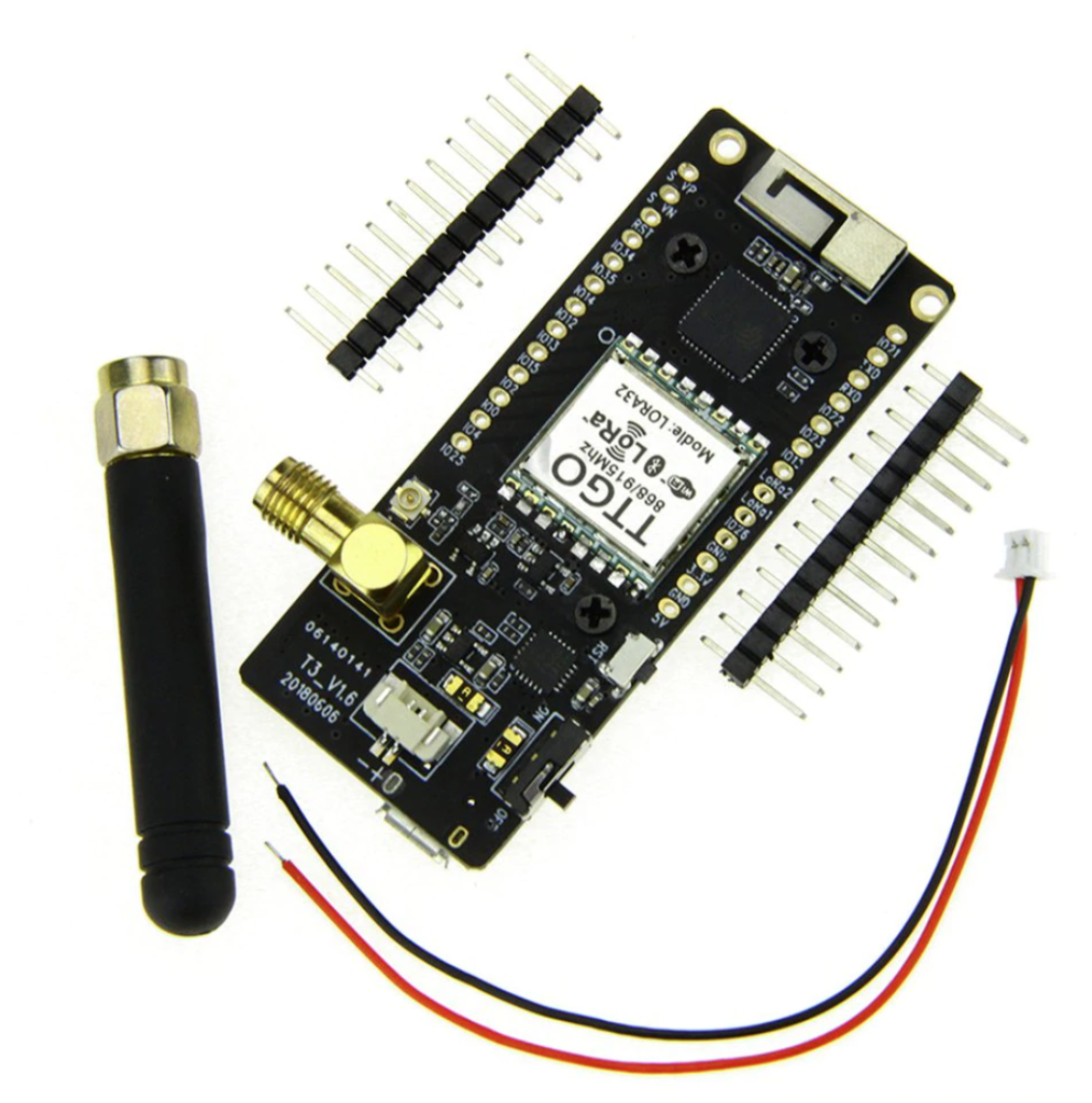
What helps me getting started fast is a selection of Arduino compatible microcontroller development boards in my toolbox. This is a 12$ Lora Board from Aliexpress. Already equipped with a display, an SMA Antenna and switches.
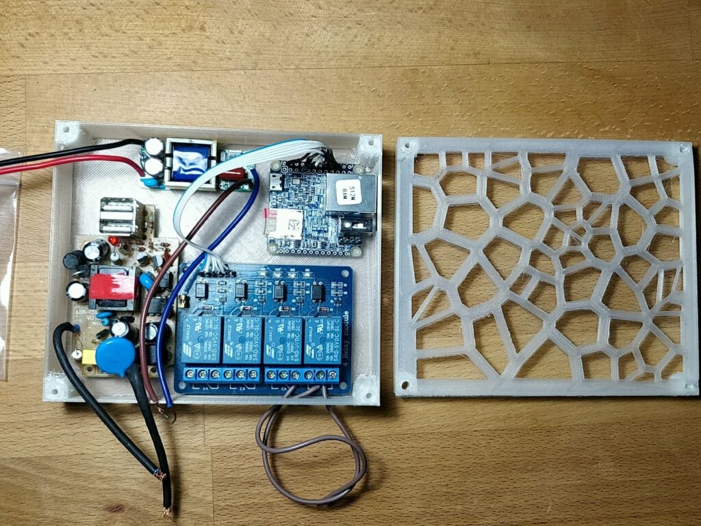
A case protects your electronic prototypes from external influences like water, sun and people/cats touching it.
NanoPi Neo with power supply. I would not recommend putting in a power supply like this. This is too much (dangerous) pfusch and I replaced it with an external power supply.
Strain Release on external cables
There’s nothing more annoying than having to debug loose cables. Fixate your loose cables with Zip Ties on the case. Mechanical forces on cables can damage solder joints – and in the worst case damage the component to a degree that you can call it garbage. Sometimes a simple drop of hot glue can prevent this. It’s not the nicest way – i prefer zip ties, but its damn quick.
Breadboard or Perfboard?
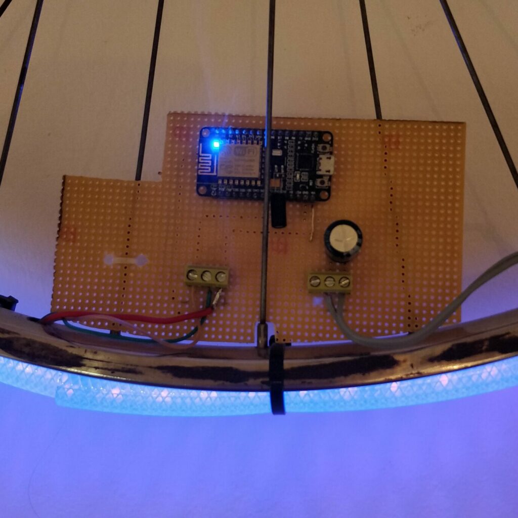
You could solder your project on perfboard. This is great for smaller project with a defined scope – everything that just has two or three components and definitely won’t get overly complicated in the near future qualifies for perfboard. The big advantage of perfboard is its robustness. Once a part is soldered on, it’s likely it won’t wiggle loose.
Perfboard mounted prototype of wled bike decoration.
4 components – low complexity. Low chance for failure.
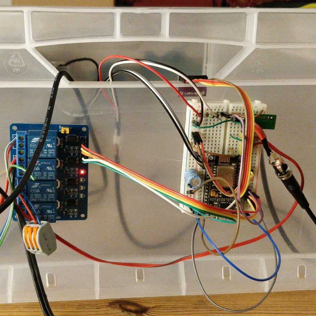
Breadboard mounted prototype of mushroom grow box.
10 components – more complex. I2C communication, separate power supply: Higher chance of failure.
Firmware
If it should be a quick prototype, try to avoid writing code as much as possible! I know, it’s fun – but try to avoid happy engineering. It’s sometimes quicker to use already existing software. For many automation tasks you can use esphome. ESPHome creates a custom firmware on demand, provides Over-the-air firmware updates, an API to access sensor data, simple preprocessing/filtering of data, and a rules engine to trigger events. It is possible to build robust, functional prototype firmware within minutes with this approach. All you have to do is writing a yaml file with your component configuration.
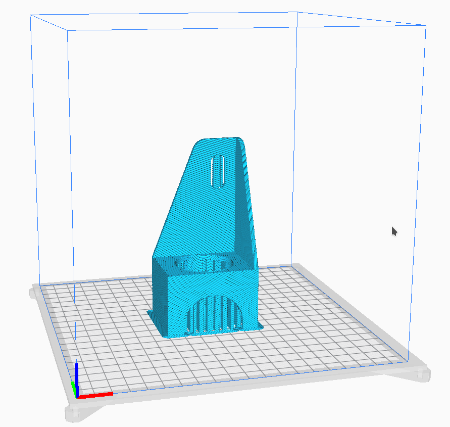
Use 3D printing – and Laser Cutting if you can
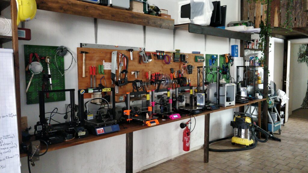
Getting started with 3D printing requires some training, but it’s worth it. The learning curve is steep and the results will benefit your project immediately. Operating a 3D printer is only half the story.
In many cases you want to design special parts for your project. You won’t find those 3D Models on Thingiverse; you’ll have to design it yourself. I find the Software Fusion360 the most useful.
Makerspaces like the xHain are a good place to connect to people and learn more about 3D printing.
Learning to design a simple, structural part in Fusion360 is relatively easy. Start with a Sketch and use the history function to modify dimensions / contours in the timeline.
This is my favorite tool
The finished CAD Model goes straight into a slicer software. I like to use Cura for it’s simplicity. The slicer is creating machine code – instructions for the printers controller to turn on fans, heat beds, nozzles and move motors etc… (BTW: Great hacking potential – take a look what else you can do with g-code)
Have you been in the situation where you start an app and want to intercept network traffic because you are curious what messages are exchanged between the client and the API? So you spin up mitmproxy, charlesproxy, burpsuit or whatever and you see.. nothing?? Hmm, that might be because certificate pinning implemented in the client. Luckily there are some methods to bypass that. One method, that sometimes works for Android apps is to patch the app.
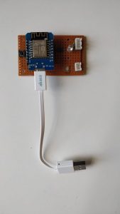
get it
My preferred way to get an APK from an Android device (for reverse engineering purposes etc) is this helpful bash script. No root required, adb installed, phone in developer mode.
This steps generates smali code. Smali is an assembler for Dalvik Virtual Machine bytecode; The assembled dex (Dalvik executable) bytecode can be decompiled into smali code. That’s what we are doing now.
Ok, now that we have the smali code, we can start browsing where the app checks the x.509 certificate. “checkClientTrusted” and “checkServerTrusted” are really good candidates. We patch those two functions to return before the actual check executes by adding “return-void” (line 453 and 467)
compile it
apktool b targetapp -o modfied_targetapp.apk
sign it
First, we generate a key and then we use jarsigner to sign the apk
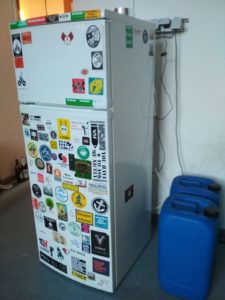
The smart fridge is here! No displays, no stupid useless functionality – but precise temperature control and monitoring.
A Fridge is a very simple device. It’s a refrigerating compressor that is turned on and off by a thermostat. Turing on the compressor leads to a drop in temperature, which is monitored by the thermostat. If the target temperature is reached, the thermostat cuts the 230V power and the compressor turns off. Naturally, the temperature is rising again and the cycle start all over again.
This temperature range between compressor on and off is not precise enough for our needs. Therefore, we will replace the old thermostat with a microcontroller and a relay. As a nice benefit, this also allows us to monitor the temperature and change the target temperature from remote.
Part 1: Hacking the Fridge
If you want to learn more about how a fridge works, checkout https://www.brewpi.com/fridge-hacking-guide/. Most of this sections part is identical to the guide above and they did a really good job describing how fridges work.
Parts:
2x DS18B20 Temperature Sensor
2x XLR 3-Pin Connector pair
Wemos D1 mini
USB Power Supply
Solid State Relay
Silicone for insulating and closing the old cable hole of the thermostat.
1x 4K7 Ω Resistor
Replacing the old thermostat with a Relay
Time to rip out the old thermostat:
For easy cleaning, we want to make the temperature probes removable. XLR connectors are a cheap and reliable way to attach sensors if you only require 3 lines. An advantage of using DS18B20 sensors is, that they are using a 1-wire bus. That means we can add many sensors and still require only one long cable from the fridges connector panel to the controller board.
Part 2: Building the Controller Board.
The controller board is in charge of monitoring the 2 temperature probes, reporting the temperature values to the cloud and of course, switching the compressor relay.
Our main controller, the Wemos D1 mini is based on an ESP8266 SoC, has multiple GPIO Pins exposed and WiFi onboard. This allows us to add more sensors later. For example, we could add an MHZ 19 CO2 Sensor into the fridge to check when the fermentation started without opening the door. But for now, we only need 4 of those pins to control our smart fridge.
1 Pin for a status LED to check the current status and inform about problems.
1 Pin to add a button for simple control like resetting, thermostat on/off, enter configuration mode etc..
1 Pin for the temperature probes. We are using digital temperature sensors (DS18B20) and a 1-Wire protocol, so we can put multiple probes on one pin.
Relay to control the compressor.
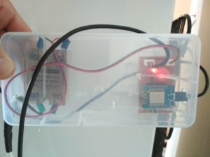
Finished controller board.Solid State Relay (left) is switching the compressor.
Part 3: Software Setup
After flashing the Wemos with the standard “sonoff.bin” build of Tasmota, we are ready to create the rule set for the thermostat. But first, let’s check if the temperature probes are working. We can go the easy way and use the built-in web interface, the serial console or we can do it more complicated. Like this:
Now that everything is running, let’s configure the thermostat. For this, we need to set some basic configuration. We use the backlog command to queue and execute all settings together. This avoids restarts.
SwitchMode1 3: Configure the switch to send a toggle command when the switch is released
Rule 1: Turn on rules
Rule 4: turn off one-shot rule
TelePeriod 60: MQTT telemetry interval sent every 60 seconds. This includes the temperature sensor data and will trigger the thermostat later.
SetOption26 1: Use an index on the relay. If we receive an MQTT message, tasmoa will know which relay to switch and use POWER1 instead of POWER
SetOption0 0: Disable saving the power state, because…
poweronstate 0: …after a restart, the relay should always be off.
mem1 0; mem2 18; mem3 16: We can store up to 5 variables in the flash memory. mem1 is used to enable (1) or disable (0) the thermostat. This can be set by MQTT: Publish a 1 or a 0 to cmnd/sonoff/mem1. mem2 and mem3 are the upper and lower setpoints of the thermostat.
var1 0: This is a variable, which allows us to check it the thermostat is usable. 1 means OK and 0 means not ready. Subscribe to cmnd/sonoff/var1 to check the status. A reason why the thermostat might not be ready is, that the temperature sensor can’t be found.
The groundwork is done. Let’s create a rule. You can configure up to 5 rules; we are using Rule1. It’s simple, you create one big line with all the conditions and actions:
Rule1 on system#boot do RuleTimer1 70 endon on Switch1#State do event toggling1=%mem1% endon on event#toggling1=0 do mem 1 endon on event#toggling1=1 do mem 0 endon on Rules#Timer=1 do backlog var1 0; RuleTimer1 70; power1 0 endon on tele-DS18B20-1#temperature do backlog var1 1; RuleTimer1 70; event ctrl_ready=1; event temp_demand=%value% endon on event#ctrl_ready>%mem1% do var1 0 endon on event#temp_demand>%mem2% do power1 %var1% endon on event#temp_demand<%mem3% do power1 0 endon
Explanation:
Rule1: Use Rule1
on system#boot do RuleTimer1 70 endon: When the systems starts, start a Timer that either evaluates the rules or only Rule1. If you can figure this out, let me know in the comments.
on Switch1#State do event toggling1=%mem1% endon: The moment, the state of Switch1 changes,
Part 4: Using it!
The setpoints can be controlled either by using the built in webserver or MQTT. The webserver has a virtual command prompt. To set the thermostat to an upper setpoint of 18 degrees Celsius and a lower setpoint of 16 degree, write
mem2=18
mem3=16
Finally, if not done yet, write
mem1=1
to activate the Thermostat. Alternatively, you can also press the button on the control board once.
AAAAAAAND here we come to a stop. The summer semester 2019 has ended and the rooms are locked down until winter semester. Everyone let’s go to the beach! This post will hopefully be continued soon. Stay tuned!
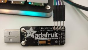
I wanted to document the steps that are necessary to transform the Adafruit Bluetooth LE Friend (https://www.adafruit.com/product/2267) to an passive Bluetooth 4.0 Low Energy Sniffer device. This sniffer can be used to monitor the bluetooth communication between 2 LE devices. Which makes it a useful and cheap tool for security research and development.
The Bluetooth LE Friend comes in 2 versions – one with a preinstalled Bootloader, Softdevice and Application to control the on-board Nordic nRF51822 chipset using AT Commands. This Is already really useful for prototyping your own bluetooth applications. It supports OTA updates and Adafruit provides an Android application together with some demo projects.
SWD Programmer (In this example, we are using the STLink V2)
openocd installed
Adafruits Adalink Tool
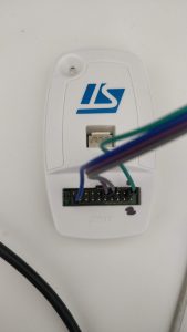
Step 1: Wire up your programmer
I’m using the STLink V2 SWD programmer (the white box).
Wired up ST-Link adapter
You need to connect 4 lines to it.
Ground (Blue)
Target Voltage for sensing (Green)
SWCLK (Purple)
SWDIO (Grey)
Now, you need to connect those lines to the SWD connection pads on the bottom of the PCB of your LE Friend. Soldering them on is the fasted way in my opinion.
Adafruit Bluetooth LE Friend v3 with soldered on SWD pins
Note that we don not need to connect the reset pin – the reset is done via the SWDIO line.
Step 2: Prepare
For simplicity, you’ll flash the LE Friend using Adalink. (https://github.com/adafruit/Adafruit_Adalink). Adalink is a python wrapper for OpenOCD that abstracts away the complexity of OpenOCD – which is good and bad a the same time.
The Booloader (https://raw.githubusercontent.com/adafruit/Adafruit_BluefruitLE_Firmware/03110f6819d2e8c0928ce1f3879df22dab562447/bootloader/bootloader_0002.hex)
The Sniffer Firmware (https://raw.githubusercontent.com/adafruit/Adafruit_BluefruitLE_Firmware/03110f6819d2e8c0928ce1f3879df22dab562447/sniffer/1.0.1/ble-sniffer_nRF51822_1.0.1_1111_Sniffer_No32kHz.hex)
Save those files – you’ll need them in the next step.
Step 3: Flash the firmware
Connect your Programmer with your computer and Plug the LE Friend into USB – This powers the nrf51 – the programmer alone does not provide any power to the LE Friend.
As I said, I’m not a big fan of abstracting complicated tasks away from the Hacker: A look under the hood of Adalink reveals what it does. Based on your programmer, it loads the necessary target and board configuration (the -f flags) and executes a bunch of commands (the -c flags). The call above results in 2 subprocess calls:
1: The wipe command in adalink for the stlink adapter:
If everything worked, the Bluefruit LE should boot with the sniffer firmware after the reset and you should see the blue led flickering – this indicates that you were successful.
I needed a lamp. And I wanted to build it myself. I’ve found a couple cool lamps on Thingiverse, but the one I liked provided unprintable, broken models. So I started Thingiverse and built my own model.
For the wood, i’ve used 5mm square mahogany timber from my favourite art supply store Modulor.
The setup consists of 2 layers with 5 leds each. Those chip leds get really hot, so they need some heatsinks. A 3D printed socket for the leds holds the heatsink in place. You can download the .stl here.
For those who missed it – the 33rd Chaos Communication Congress took place from 27.-30.12.2016 – and it was the last one in Hamburg. And I got a ticket. I haven’t seen a lot of talks, because I spent most of my time walking around the hack area and talking to people. But here are some of the talk highlights that I can recommend:
1: Shut Up and Take My Money! – The Red Pill of N26 Security
…or how a broken authentication system could lead to corrupt transactions.
2: SpiegelMining – Reverse Engineering von Spiegel-Online
David Kriesel, who presented the lovely talk about the Xerox Scanner Bug at 31C3, demonstrates how he used big data to determine internal structures of the Spiegel publishing company. Must see!
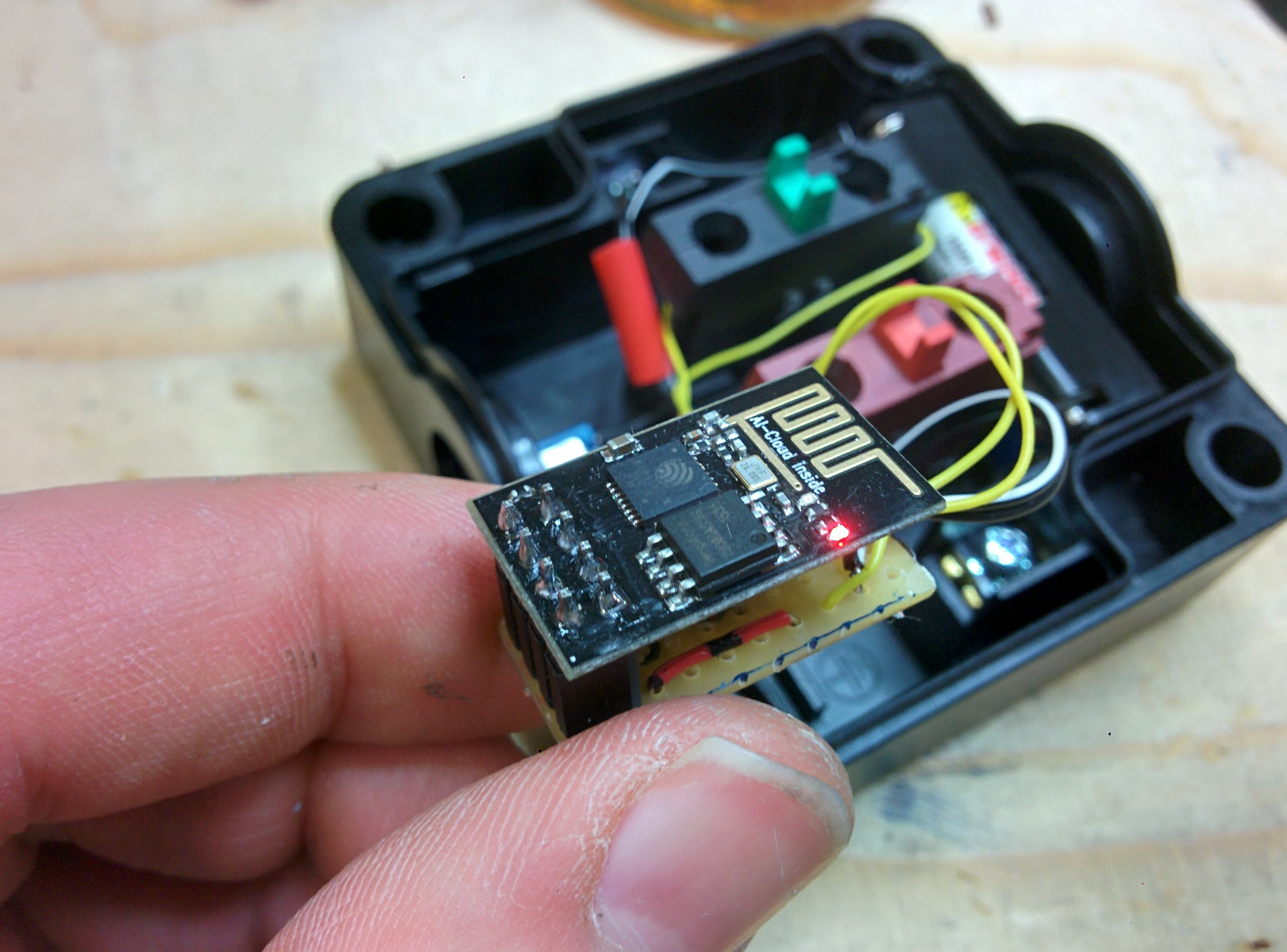
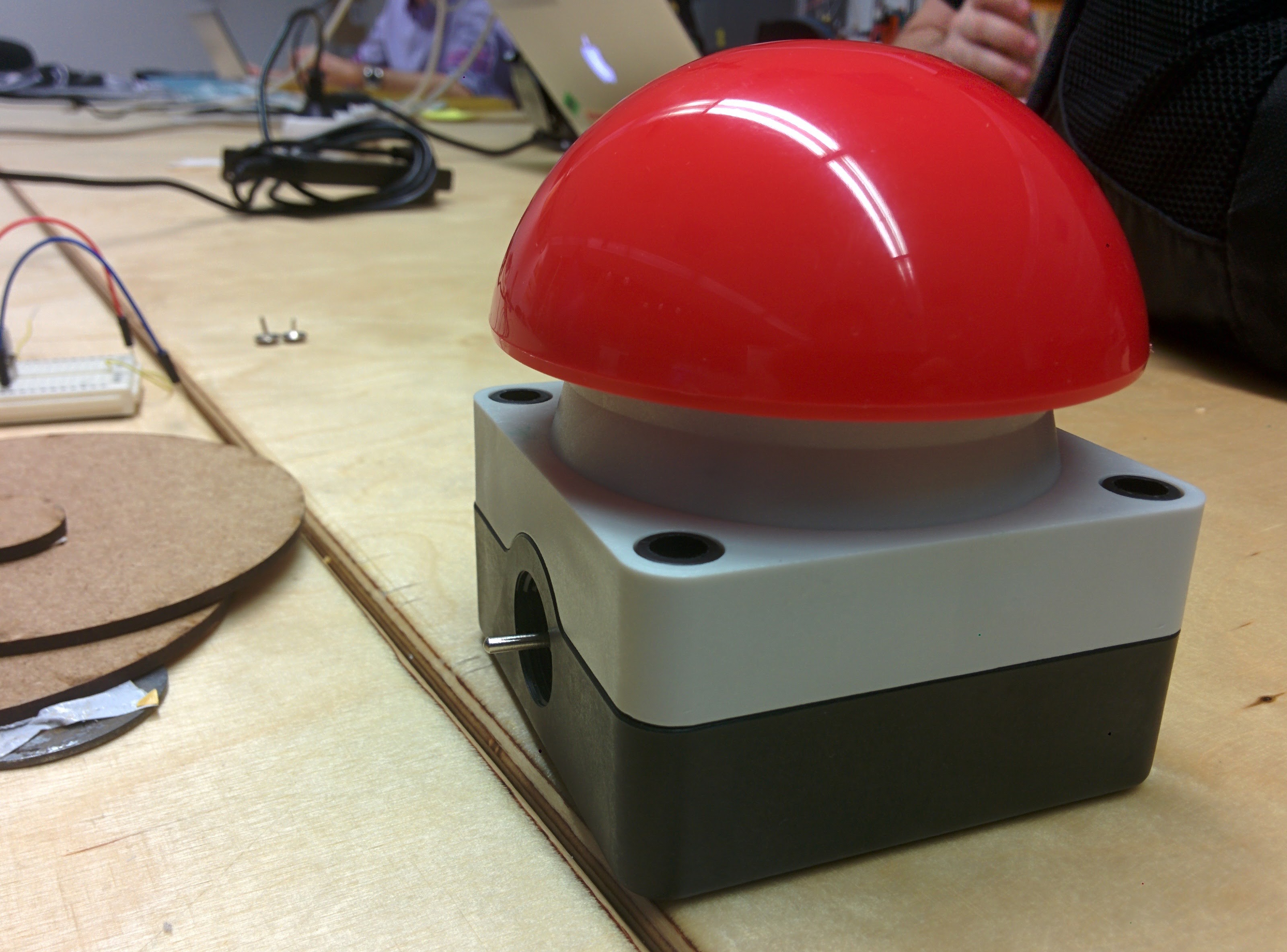
I’ve built an IoT button a while ago. I’ve also written a short log of the project on hackday.io
The ESP8266, which is used here, is a small, WiFi-enabled chip which can be programmed. I hooked it up to send web request to IFTTT to trigger actions.
I started with a prototype on a ESP8266 NodeMCU development board. The button causes the ESP to send a web request to IFTTT, which is configured to send a push notification to my iPad in this example, but can trigger nearly any action that is supported by IFTTT.
after testing the firmware on the development board, I flashed it on the chip and put everything together.
IFTTT SmartButton from the inside.Tada! We do now have a battery powered push button for the internet of things.