
I’ve read many articles on how to build IoT projects with Arduino – most of them covered the basics of micro controllers and how to use them in a more or less useful scenario in your home (“Build a self watering plant with an Arduino”). I’ve always missed the HOW part. That’s why I want to summarize my own experiences and mistakes made. I want to give you some tips on how to avoid problems building very quick prototypes to try a certain use case. See this article as a collection of thoughts and not as the definite truth.
In my understanding, Rapid Prototyping is the process of building a working “system” of some sort in relatively little time with the goal of experiencing how this system feels in a certain scenario and learn from this experience. The outcome of this process is not a product but knowledge about usability, haptics and possible problems in operation and manufacturing.
With that said, let me summarize some of my thoughts:

Use existing modules
Aliexpress is your friend. I recommend getting a basic setup of those small and really cheap modules for your project domain. It won’t cost you a fortune to get a few. Always order a bunch – you will break stuff. And shipping from china takes a few weeks.
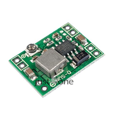
Often, people struggle with the power supply of your project. DC DC Buck converters allow you to transform a higher voltage from a variable input to your desired one. They cost about 0.30 Euro / piece and can be useful in cases where you need to run a 3.3V MCU on 12V DC.

The other way is also possible with a step up converter (sometimes referred to as boost converter). It lets you boost your voltage from a lower voltage to a higher one. For example, you have a USB powered device and you want to run a 12V Fan on it. On this 1.80 Euro module, the output voltage can be adjusted with the potentiometer.
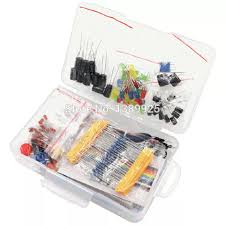
Get a bunch of capacitors and resistors. They are your friends. A good kit contains
- 470 μF (can minimize reset inducing voltage fluctuations)
- 0.1 μF (standard decoupling capacitor)
- 1 kΩ Resistor
- 10 kΩ Resistor (good Pullup for 5V apps.)
- 100
- 470 kΩ Resistor
- 4.7 kΩ Resistor
I found that 10 kΩ to 100 kΩ pullup resistors usually work fine in my circuits.
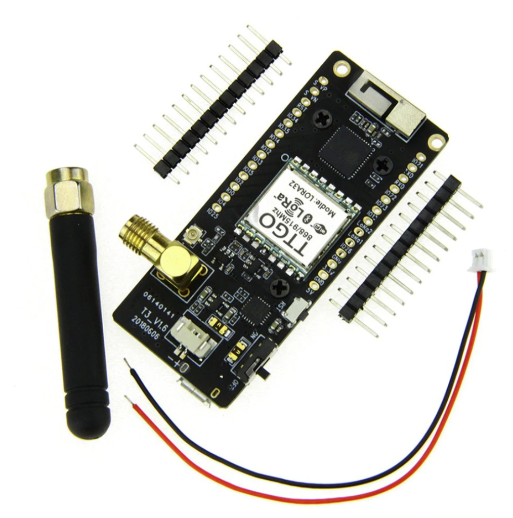
What helps me getting started fast is a selection of Arduino compatible microcontroller development boards in my toolbox. This is a 12$ Lora Board from Aliexpress. Already equipped with a display, an SMA Antenna and switches.
Checkout this post from Seedstudio – they cover some, but not all, MCU boards for 2020
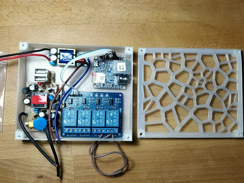
Put it in a case.
A case protects your electronic prototypes from external influences like water, sun and people/cats touching it.
Strain Release on external cables
There’s nothing more annoying than having to debug loose cables. Fixate your loose cables with Zip Ties on the case. Mechanical forces on cables can damage solder joints – and in the worst case damage the component to a degree that you can call it garbage. Sometimes a simple drop of hot glue can prevent this. It’s not the nicest way – i prefer zip ties, but its damn quick.

Breadboard or Perfboard?
You could solder your project on perfboard. This is great for smaller project with a defined scope – everything that just has two or three components and definitely won’t get overly complicated in the near future qualifies for perfboard. The big advantage of perfboard is its robustness. Once a part is soldered on, it’s likely it won’t wiggle loose.
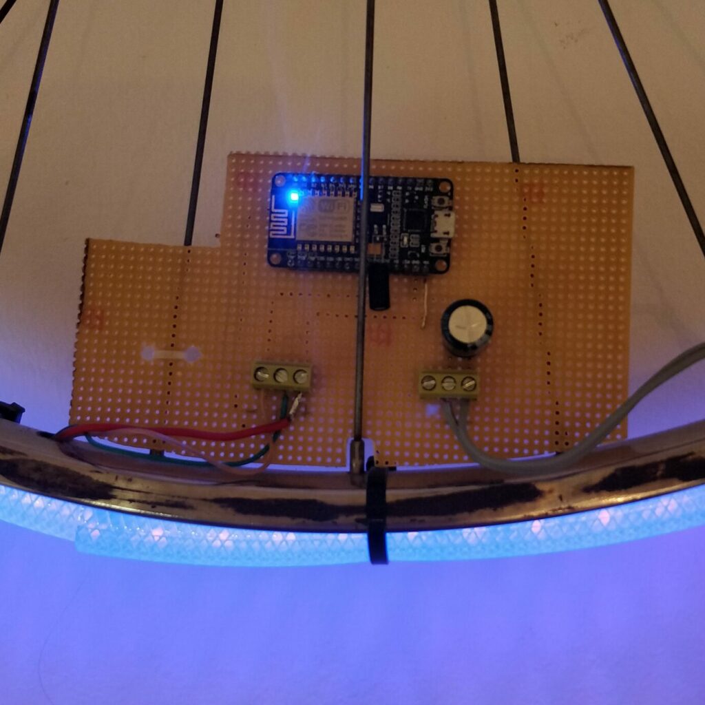
4 components – low complexity. Low chance for failure.
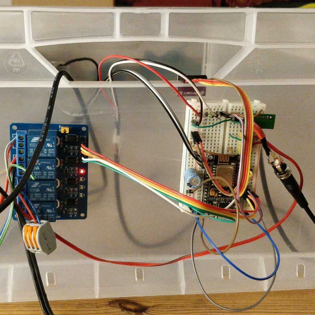
10 components – more complex. I2C communication, separate power supply: Higher chance of failure.
Firmware
If it should be a quick prototype, try to avoid writing code as much as possible! I know, it’s fun – but try to avoid happy engineering. It’s sometimes quicker to use already existing software. For many automation tasks you can use esphome. ESPHome creates a custom firmware on demand, provides Over-the-air firmware updates, an API to access sensor data, simple preprocessing/filtering of data, and a rules engine to trigger events. It is possible to build robust, functional prototype firmware within minutes with this approach. All you have to do is writing a yaml file with your component configuration.
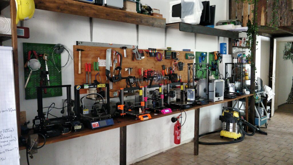
Use 3D printing – and Laser Cutting if you can
Getting started with 3D printing requires some training, but it’s worth it. The learning curve is steep and the results will benefit your project immediately. Operating a 3D printer is only half the story.
In many cases you want to design special parts for your project. You won’t find those 3D Models on Thingiverse; you’ll have to design it yourself. I find the Software Fusion360 the most useful.
Learning to design a simple, structural part in Fusion360 is relatively easy. Start with a Sketch and use the history function to modify dimensions / contours in the timeline.
The finished CAD Model goes straight into a slicer software. I like to use Cura for it’s simplicity. The slicer is creating machine code – instructions for the printers controller to turn on fans, heat beds, nozzles and move motors etc… (BTW: Great hacking potential – take a look what else you can do with g-code)
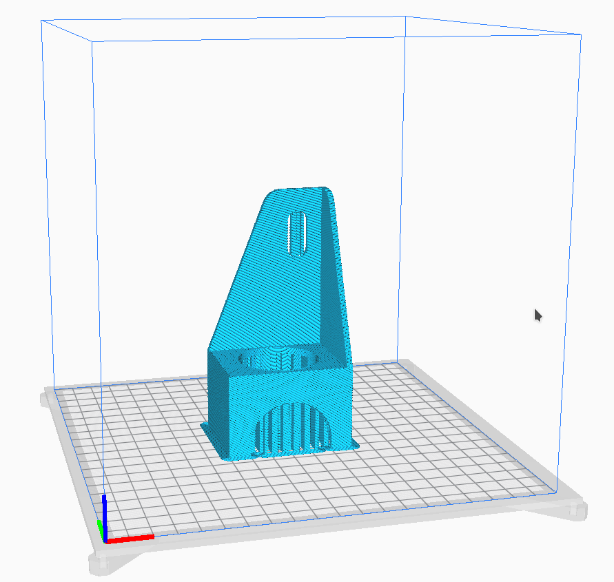
From there on, hit print and wait….

I hope this gave you some inspiration.