

The smart fridge is here! No displays, no stupid useless functionality – but precise temperature control and monitoring.
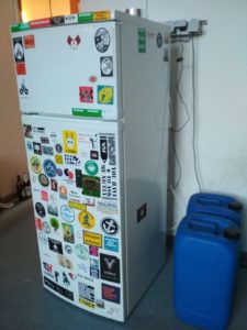
A Fridge is a very simple device. It’s a refrigerating compressor that is turned on and off by a thermostat. Turing on the compressor leads to a drop in temperature, which is monitored by the thermostat. If the target temperature is reached, the thermostat cuts the 230V power and the compressor turns off. Naturally, the temperature is rising again and the cycle start all over again.
This temperature range between compressor on and off is not precise enough for our needs. Therefore, we will replace the old thermostat with a microcontroller and a relay. As a nice benefit, this also allows us to monitor the temperature and change the target temperature from remote.
Part 1: Hacking the Fridge
If you want to learn more about how a fridge works, checkout https://www.brewpi.com/fridge-hacking-guide/. Most of this sections part is identical to the guide above and they did a really good job describing how fridges work.
Parts:
- 2x DS18B20 Temperature Sensor
- 2x XLR 3-Pin Connector pair
- Wemos D1 mini
- USB Power Supply
- Solid State Relay
- Silicone for insulating and closing the old cable hole of the thermostat.
- 1x 4K7 Ω Resistor
Replacing the old thermostat with a Relay
Time to rip out the old thermostat:

For easy cleaning, we want to make the temperature probes removable. XLR connectors are a cheap and reliable way to attach sensors if you only require 3 lines. An advantage of using DS18B20 sensors is, that they are using a 1-wire bus. That means we can add many sensors and still require only one long cable from the fridges connector panel to the controller board.

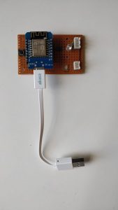
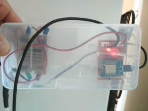
Part 2: Building the Controller Board.
The controller board is in charge of monitoring the 2 temperature probes, reporting the temperature values to the cloud and of course, switching the compressor relay.
Our main controller, the Wemos D1 mini is based on an ESP8266 SoC, has multiple GPIO Pins exposed and WiFi onboard. This allows us to add more sensors later. For example, we could add an MHZ 19 CO2 Sensor into the fridge to check when the fermentation started without opening the door.
But for now, we only need 4 of those pins to control our smart fridge.
- 1 Pin for a status LED to check the current status and inform about problems.
- 1 Pin to add a button for simple control like resetting, thermostat on/off, enter configuration mode etc..
- 1 Pin for the temperature probes. We are using digital temperature sensors (DS18B20) and a 1-Wire protocol, so we can put multiple probes on one pin.
- Relay to control the compressor.
Part 3: Software Setup
After flashing the Wemos with the standard “sonoff.bin” build of Tasmota, we are ready to create the rule set for the thermostat. But first, let’s check if the temperature probes are working. We can go the easy way and use the built-in web interface, the serial console or we can do it more complicated. Like this:
mosquitto_sub -h $MQTT_HOST -t '#' -u fridge -P $_MYMQTTPASSWD -F '%t -> %p'
Here, we subscribed to the MQTT broker directly. I like this way of debugging since you get to see what’s actually going on on the message bus.
After a while, we expect to see a message like this:
tuberlin/beer/tele/SENSOR ->
{
  "TempUnit" : "C",
  "Time" : "1970-01-01T00:34:16",
  "DS18B20-2" : {
    "Id" : "0517B02035FF",
    "Temperature" : 12.5
  },
  "DS18B20-1" : {
    "Id" : "0517B01741FF",
    "Temperature" : 15.3
  }
}
Now that everything is running, let’s configure the thermostat. For this, we need to set some basic configuration. We use the backlog command to queue and execute all settings together. This avoids restarts.
backlog SwitchMode1 3; Rule 1; Rule 4; TelePeriod 60; SetOption26 1; SetOption0 0; poweronstate 0; mem1 0; mem2 25; mem3 23; var1 0
Explanation:
- SwitchMode1 3: Configure the switch to send a toggle command when the switch is released
- Rule 1: Turn on rules
- Rule 4: turn off one-shot rule
- TelePeriod 60: MQTT telemetry interval sent every 60 seconds. This includes the temperature sensor data and will trigger the thermostat later.
- SetOption26 1: Use an index on the relay. If we receive an MQTT message, tasmoa will know which relay to switch and use POWER1 instead of POWER
- SetOption0 0: Disable saving the power state, because…
- poweronstate 0: …after a restart, the relay should always be off.
- mem1 0; mem2 18; mem3 16: We can store up to 5 variables in the flash memory. mem1 is used to enable (1) or disable (0) the thermostat. This can be set by MQTT: Publish a 1 or a 0 to cmnd/sonoff/mem1. mem2 and mem3 are the upper and lower setpoints of the thermostat.
- var1 0: This is a variable, which allows us to check it the thermostat is usable. 1 means OK and 0 means not ready. Subscribe to cmnd/sonoff/var1 to check the status. A reason why the thermostat might not be ready is, that the temperature sensor can’t be found.
The groundwork is done. Let’s create a rule. You can configure up to 5 rules; we are using Rule1. It’s simple, you create one big line with all the conditions and actions:
Rule1 on system#boot do RuleTimer1 70 endon on Switch1#State do event toggling1=%mem1% endon on event#toggling1=0 do mem 1 endon on event#toggling1=1 do mem 0 endon on Rules#Timer=1 do backlog var1 0; RuleTimer1 70; power1 0 endon on tele-DS18B20-1#temperature do backlog var1 1; RuleTimer1 70; event ctrl_ready=1; event temp_demand=%value% endon on event#ctrl_ready>%mem1% do var1 0 endon on event#temp_demand>%mem2% do power1 %var1% endon on event#temp_demand<%mem3% do power1 0 endon
Explanation:
- Rule1: Use Rule1
- on system#boot do RuleTimer1 70 endon: When the systems starts, start a Timer that either evaluates the rules or only Rule1. If you can figure this out, let me know in the comments.
- on Switch1#State do event toggling1=%mem1% endon: The moment, the state of Switch1 changes,
Part 4: Using it!
The setpoints can be controlled either by using the built in webserver or MQTT. The webserver has a virtual command prompt. To set the thermostat to an upper setpoint of 18 degrees Celsius and a lower setpoint of 16 degree, write
mem2=18
mem3=16
Finally, if not done yet, write
mem1=1
to activate the Thermostat. Alternatively, you can also press the button on the control board once.
AAAAAAAND here we come to a stop. The summer semester 2019 has ended and the rooms are locked down until winter semester. Everyone let’s go to the beach! This post will hopefully be continued soon. Stay tuned!
RuleTimer1 is used to shut down output (turn off power1) if Temperature sensor disconnects/fails. It will resume operation when sensor is back.